Connecting modules
Using Troyka modules
There are four slots on the board for connecting modules wirelessly. The slot locations are shown on the board itself, in the pictures below, as well as in the interactive pinout.
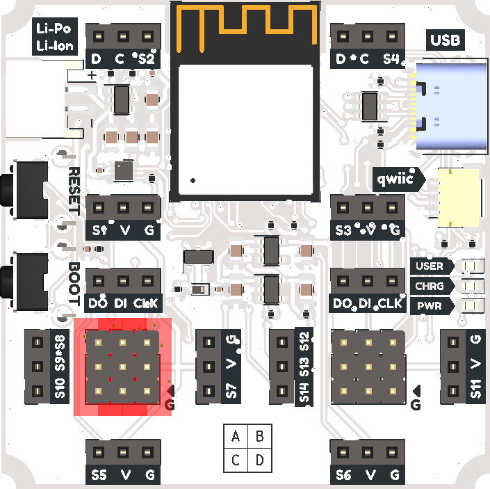
Slot A on the board
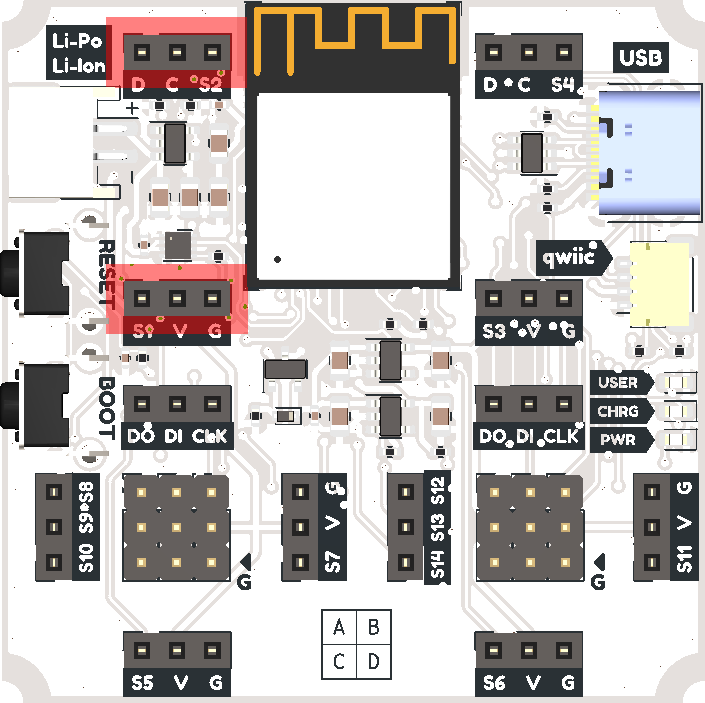
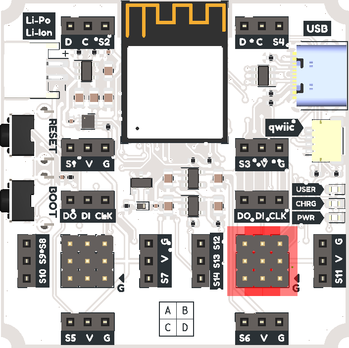
Slot B on the board
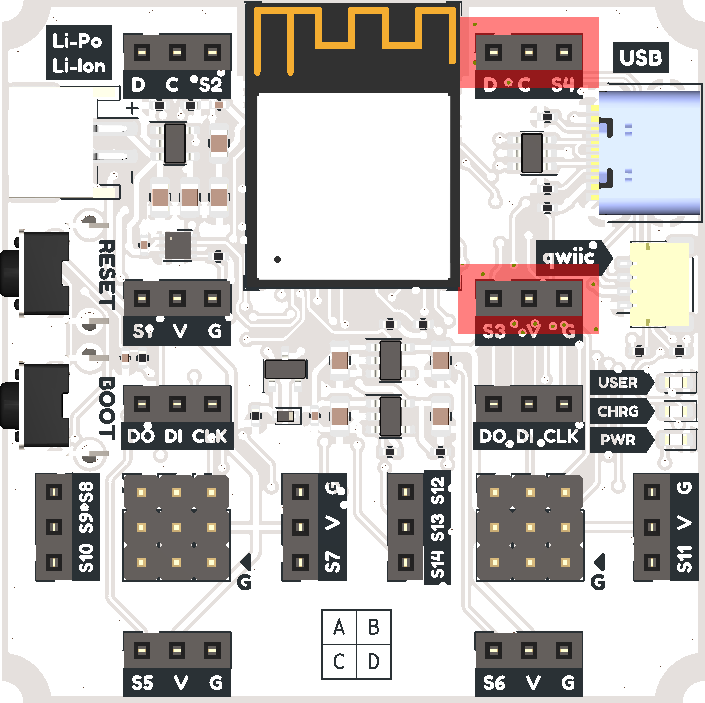
Slot C on the board
Slot D on the board
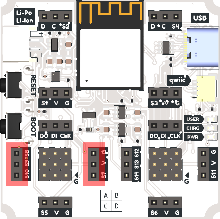
Slots C and D also have an alternative connection. If you rotate the module 90 degrees to the left, then instead of the SPI interface, more digital or analog pins or UART interface pins will be available.
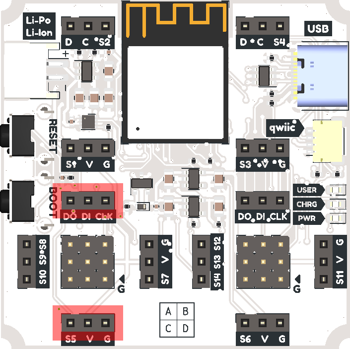
Alternative connection for slot C on the board
Alternative connection for slot D on the board
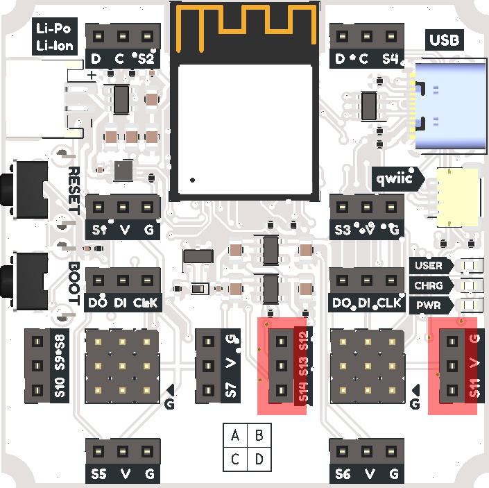
If you want to connect more modules to the board, then you can use three-pin loops to connect them to the central pins of slots C and D.
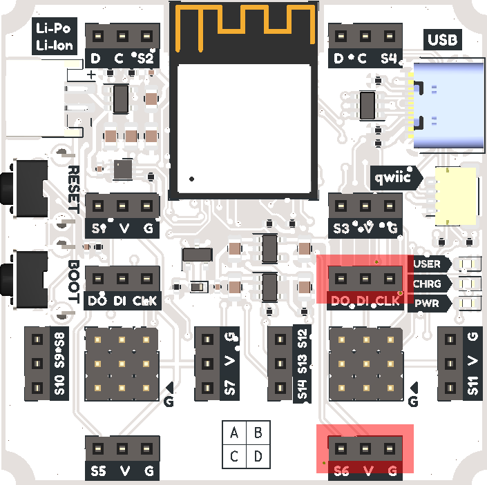
Central pins of slot C on the board
Central pins of slot D on the board
When connecting the module, it is worth focusing on the contact G (GND). This is how you position the module correctly.
The recommended maximum current consumption for each slot is 150 mA.
Before connecting, we recommend that you familiarize yourself with the Troyka module format. If you want to create your own module, then we have prepared project templates for KiCad 6.
Using QWIIC / STEMMA QT modules
The QWIIC or STEMMA QT connector allows you to connect more various modules to the control board!
QWIIC / STEMMA QT connector on the board
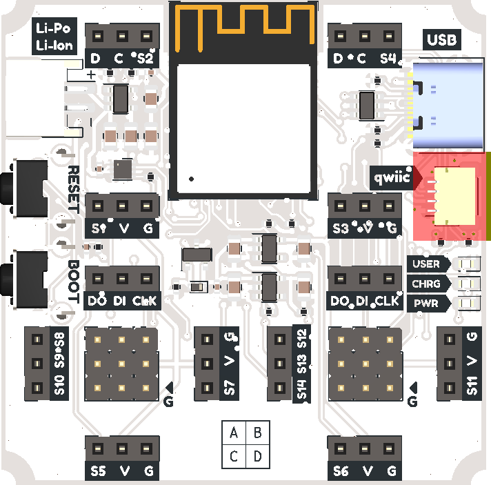
You can find out more about this format on the Sparkfun website or Adafruit.
The recommended maximum current consumption for all connected modules is 100 mA, or 200 mA if Wi-Fi is not used.